Beam Axis
Beam Axis groups collinear beams into horizontal and sloped runs, previews each run, checks it, and creates bars and optional sheets. These are real Revit 2027 screenshots; the tool supports Revit 2024–2027.
Ribbon: BimSpeed.STR → Beam → Beam Rebar menu → Beam Rebar Axis, directly below the regular Beam Rebar command.
These are full-screen Revit 2027 captures. Click either crop to open the full-resolution screenshot.
① Open BimSpeed.STR; ② click the small arrow under Beam Rebar; ③ choose the second item, Beam Rebar Axis. Clicking the main part of button ② runs regular Beam Rebar.
Download the three practice models (.zip) — use 02-Beam-Axis-Revit-2027.rvt for this exercise.
Jump to 3D preview, top/bottom bar count, stirrups, crossing roles and hangers, anchorage and laps, or buttons and settings groups. See also the settings exercise.
1. Select an axis or beams
- Open the practice model in Revit 2027. In a 3D, plan, section, or elevation view, select a Grid to load the whole axis, or concrete beams to preselect their runs.
- Click Beam Rebar Axis. If nothing is selected, pick grids or beams in the model when prompted. Linked-model beams are not supported; open the linked source file for those.
- Tick the runs in Axes & runs on the left. Use + Add axes / beams… to pick more; filter by All / Horizontal / Sloped / Warnings.

① tick runs; ② inspect the elevation and select spans/bars; ③ edit properties; ④ create bars. The span table and 1-1 / 2-2 / 3-3 sections sit below the canvas.
2. Edit the design
- Select a run, then a span, joint, or bar on the canvas or span table. The right panel breadcrumb shows Project → Axis → Run → Span / Joint / Bar. Set bar counts and diameters, stirrup zones, extra bars, and anchorage per the engineering design.
- Apply a layout template to a run or open Detailing standard… for common rules. Each field indicates inherited or overridden values; Undo in this window reverts the most recent settings edit.
- Toggle Main / Additional / Stirrups on the canvas and switch between Elevation and 3D to inspect what will be written to Revit.
Open the 3D preview
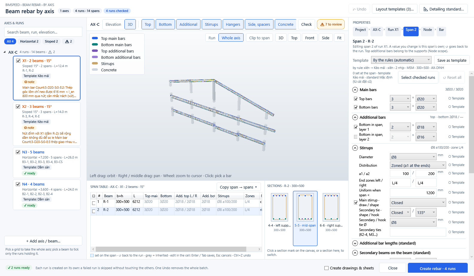
- Tick a run in Axes & runs and select its card. On the black toolbar above the drawing, click 3D next to Elevation. This is the preview inside Beam Axis, not Revit's 3D View command. The earlier overview screenshot predates this control; the marked screenshot below shows its current position.
- Choose Run / Whole axis to set scope, Clip to span for the selected span, and 3D / Top / Front / Side / Fit at the upper right to orient the camera. Left-drag orbits; right/middle-drag pans; the wheel zooms; clicking a bar opens its Bar settings.
- Top / Bottom / Additional / Stirrups / Hangers / Side, spacers / Concrete only show or hide preview layers. They do not remove bars from the Revit output. Change the actual design in Properties on the right. Turn off Concrete and unrelated layers to inspect one bar group, then check the three sections below.

① 3D mode; ② preview visibility; ③ scope and camera; ④ settings that change the output; ⑤ section checks.
Change top and bottom main bars
Select the Run card to edit all spans, or click a span on the elevation/span table and confirm Span N is highlighted in the Properties breadcrumb. Open Main bars. Top bars and Bottom bars each have an enabled checkbox, Count, and Ø. To change bottom bars in span 2 from 2Ø20 to 4Ø20, select Span 2 → Main bars → Bottom bars → Count = 4 while keeping Ø20. To reduce the top layer, edit Top bars → Count. Check the mid-span section dots and the span-table row; a span value overrides the run, and ↺ restores inheritance.
Additional bars are distinct: top support layers 1/2 belong to a Node or the table's top-left/right extra bars; bottom span layers 1/2 belong to a Span. Enable the required layer and set Count × Ø. Click an individual bar or section dot for Bar scope: choose the bar set, its first/last span, Count × Ø, left/right anchors, cross-section positions and per-span profile. Add main/additional set, Split at support, Merge, and Delete change the set structure. After increasing count or Ø, review cover and clear-spacing warnings.


Adjust stirrups
Select a Span → Stirrups. Diameter changes Ø; Distribution chooses uniform or zoned placement; a1/a2 are spacing at the two ends / mid-span in mm. Decreasing a spacing generally increases the number of stirrups in that region. End zones left/right set how far a1 extends; Uniform when span < sets the threshold below which a short span is uniformly distributed. Main stirrup draw/shape, secondary tie shape/hook, secondary/hook tie Ø, and Secondary ties (K2-4, M3…) change the cross-section shape and supplementary ties. These are separate from extra ties at a secondary beam. Apply this span's stirrups to → All spans / Remaining spans copies Ø, distribution, a1/a2 and tie shapes; end-zone lengths and Draw main remain per-span, so recheck every destination.

Crossing beam roles, hangers and extra ties
At Span → Beams met / secondary beams, choose the role of each crossing: Support splits the run into spans; Secondary enables hanger bars and local extra ties; Ignored omits that crossing. Automatic restores detection. For a secondary crossing, scroll down to Secondary beams on the beam. Hanger bars enables the group and sets Count × Ø; Extension each side controls its reach. Extra stirrups enables a local set and sets tie count × Ø; Spacing / from the face sets tie spacing and offset from the secondary-beam face. For example, 2Ø16 → 3Ø16 increases hanger count by one. These local ties are different from the span-wide a1/a2 stirrups.
Anchorage and laps
Anchorage into a support and lap between bars are different. In Detailing standard → Anchorage into supports (n × d) set separate top/bottom values for columns, walls, beams, footings, plus rule-based anchorage, minimum hook, and bottom-bar hooks at columns. n × d means n times the bar diameter. At a Run, override the support rule where required. For a sloped run's Node, Frame joints controls column hook direction, outer bars at convex joints, outer-bar lap, inner bars at concave joints, their minimum anchorage and behavior when anchorage is short. A horizontal run's ordinary node generally inherits anchorage from Run/Project.
For one selected Bar, change Left anchor Lx/Ly or Right anchor Lx/Ly in mm; split/merge at supports if the bar-set geometry needs to change. In Detailing standard → Shop & laps, set top/bottom cut zones as fractions of span L, top/bottom lap lengths in n × d, distance between laps, and stock-bar length. The cut zone sets where a bar may be divided; the lap value sets overlap length. The numbers in screenshots are sample values, not universal design values. Run Check, inspect short-anchorage findings, then create and inspect Rebar in a Revit 3D view.

What the buttons and settings groups do
| Button or group | Effect |
|---|---|
| Add axes/beams, search and filters | Select more model elements or narrow the run list. Tick the runs that Create rebar should process. |
| Layout templates / Save as template | Apply or save run defaults; a more specific Span/Bar override may still win. |
| Detailing standard | Edit the project-wide standard; save it and apply the selected profile to the project. |
| Elevation/3D layers, scope, camera, zoom | Preview controls only; no change to generated Rebar. |
| Main/Additional bars; Stirrups; Secondary beams | Change bar count/diameter/length, stirrup layout, hanger bars and local extra ties. |
| Anchorage; Frame joints; Shop & laps | Change bar-end geometry, node behavior, cut zones and overlaps. |
| Cover/spacing/rounding | Change bar placement, layer clearance, rounding and crank handling; check spacing after adding bars. |
| Side bars; Spacers; Bars by beam width | Change supplementary bar layout and automatic layer-1 count by beam width. |
| Additional bar lengths; Section positions; Drawings & sheets | Set support/span extension, section locations and optional sheet output. |
| Undo / ↺ / Reset all | Undo the latest edit or reset an override at the selected scope to inherited settings. |
| Check / Go to / Create rebar | Validate and navigate issues; Create rebar writes the checked runs to Revit. Checking itself rolls the trial write back. |
The Detailing standard window also has Profile, Duplicate, Rename, Apply to project, import/export JSON, Default and Save. The marked screenshot locates the support anchorage table, frame joints, secondary-beam defaults, the width-to-count table and Save.

3. Check, create, and inspect sheets
- Click Check on the canvas toolbar. The trial write is rolled back. Review Errors / Warnings / Notes by axis, run, span, or joint; Go to takes you to the issue.
- If drawings are needed, tick Create drawings & sheets at the bottom. Click Create bars · N runs. Runs with errors are reported first. Each run is created separately; the batch is a single Revit Undo step.
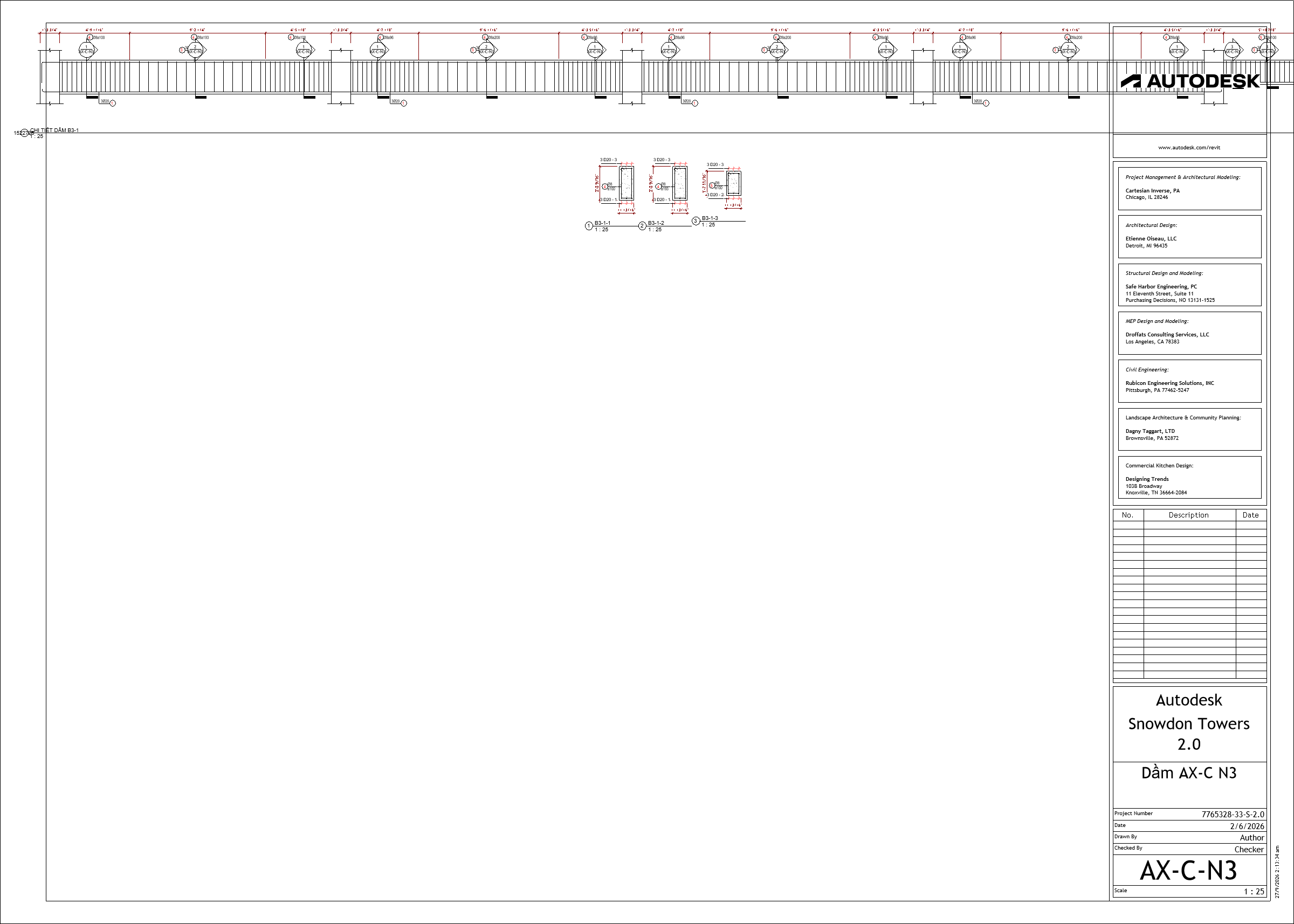
- Inspect the bars in a Revit 3D view. If sheets were enabled, find one sheet per run, for example
AX-C-N3. Rerunning a run replaces this tool's previous bars for that run.

① checking/view controls; ② span and section details and findings; ③ create bars.
The tool does not check strength, cracking, material-dependent anchorage/laps, or seismic resistance. Frame-joint detailing rules are proposals for an engineer to confirm.