Beam Rebar Classic — Quick Setting and detail editor
Classic is the earlier beam-reinforcement variant, separate from Beam Rebar and Axis. It requires a 3D view, a valid beam run and the corresponding entitlement. Edit new-tool reinforcement with its own tool or select different hosts for Classic.
Evidence scope: Actual VI/EN Quick Setting and English detail-editor captures are available. Classic reinforcement was created, saved and reopened on a native project beam in Revit 2024.3: two D20 sets (two bars each) and one D8 set (41 positions). This checks the creation controller; ribbon launch was not retested. Some Vietnamese labels remain in the real English UI.
The original Quick Setting reference is from Revit 2027.3; the new detail editor and saved-result captures below are from Revit 2024.3. Revit was maximized and dialogs retained their natural size.
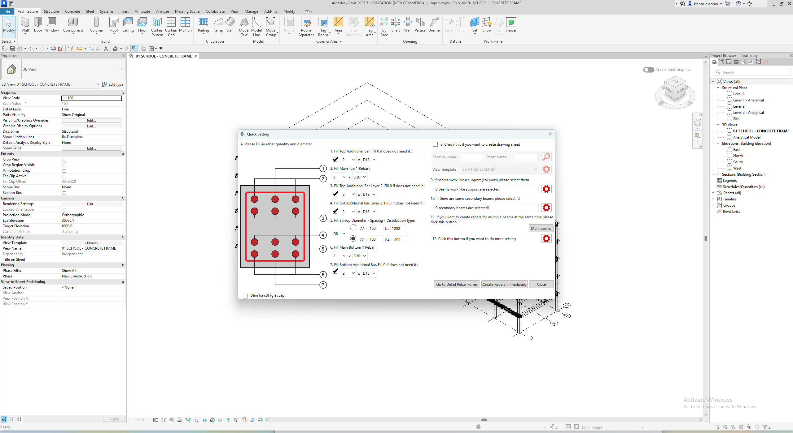

- Choose quantities and bar types for the upper groups; the checkboxes beside rows 1/3 enable additional layers. Black circled 1–7 belong to the original section diagram, separately from the red marks.
- Choose the stirrup type and A1 + L or A1 + A2 mode, then check main/additional bottom bars in rows 6/7.
- Enable drawing-sheet creation only when needed, then supply Sheet Number, Sheet Name and View Template.
- Use the row 9/10 gears for support/secondary beams; Multi beams adds scope; the row 12 gear opens Classic settings.
- Go to Detail Rebar Forms opens the span editor; Create Rebars Immediately requests model reinforcement; Close leaves Quick Setting.
Every setting and action
| Control | Effect and verification |
|---|---|
| 1 — Top additional bars | Enable upper additional bars and choose quantity/type; 0 where permitted omits that group. |
| 2 — Main top bars | Main top bar quantity/type. |
| 3 — Top additional layer 2 | Enable the second upper additional layer with its own quantity/type. |
| 4 — Bottom additional layer 2 | Enable the second lower additional layer with its own quantity/type. |
| 5 — Stirrup diameter | Choose the stirrup RebarBarType. |
| A1 + L | Distribution mode using A1 spacing and zone length L in mm. |
| A1 + A2 | Two-spacing distribution mode; inspect end/middle zones in the detailed editor and model. |
| 6 — Main bottom bars | Main bottom quantity/type, separate from additional bottom bars in row 7. |
| 7 — Bottom additional bars | Enable and configure additional bottom reinforcement. |
| 8 — Create drawing sheet | Enable associated drawing-sheet creation; supply Sheet Number, Sheet Name and View Template when enabled. |
| Sheet search / drawing gear | Find a sheet or open drawing settings. These popups have not been captured in this batch. |
| 9 — Support beams gear | Select support beams and inspect the selected-support count. |
| 10 — Secondary beams gear | Select secondary beams, separate from supports and the main run. |
| 11 — Multi beams | Select additional beams for multiple-beam operation; still validate each run. |
| 12 — More settings gear | Open Classic settings; current-version screenshots do not prove Classic settings. |
| Dầm hạ cột (giật cấp) | Stepped/lowered-beam option; this label remains Vietnamese in the actual EN capture. |
| Go to Detail Rebar Forms | Open the detailed editor; this does not itself prove model reinforcement creation. |
| Create Rebars Immediately | Create directly from Quick Setting after validation. The creation controller and saved native output were checked in the Revit 2024.3 example below; the ribbon launch was not retested. |
| Close | Close Quick Setting; its schematic is not a reinforcement result. |
Configuration shown
Captured 2D20, 2D18 and D8 a100/a200 are loaded settings. This batch has no downloadable Classic reinforcement result. Reuse the inspection principles from Beam Rebar, but do not transfer evidence between commands.
Prepare, select and run
- Save an RVT copy and open a 3D view showing the full run. Choose BimSpeed.STR → Beam → Beam Rebar Classic; when an edition labels both commands Beam Rebar, check the Quick Setting window and variant before entering data.
- Pick the concrete beams in the intended run and Finish. Include the continuous spans; support and secondary beams are selected separately in Quick Setting. Esc cancels picking.
- If the command reports bars from the new Beam Rebar, use Beam Rebar to edit those bars or select different hosts for Classic. Do not stack both tools' cages on the same host merely to proceed.
- Enter each reinforcement group and disable unused additional-layer checkboxes. To compare 2 versus 3 main top bars, change row 2 while keeping the diameter. For denser middle stirrups, keep A1 and reduce A2 from 200 to 150 mm. These describe configuration changes; the screenshots do not verify generated comparisons.
- Choose Go to Detail Rebar Forms to inspect geometry, supports, spans and bar lengths before generation, or Create Rebars Immediately when the quick configuration has been checked. Classic's detailed windows may differ from the current editor; screenshots of that editor do not verify Classic tabs.
Saved and reopened native-beam result
In Revit 2024.3, Classic from installed release 2026.10.23.2046 created reinforcement on native beam 397189 in a project copy. A new Revit process opened a copy of the saved result: all three sets retained host, type, quantity and length. No sheet was created in this example.
| Set | Type | Quantity | Bar Length | Spacing |
|---|---|---|---|---|
| 476038 | D20 | 2 | 4030.0 mm | Fixed Number |
| 476039 | D20 | 2 | 5004.25 mm | Fixed Number |
| 476040 | D8 | 41 | 2283.95 mm | 100 mm |
These three sets contain 45 bar positions. The actual stirrup spacing is 100 mm; A2 in Quick Setting alone does not establish an a200 zone. Inspect the detail editor and model Properties.

- D20 type. 2. Quantity 2 / Fixed Number of the selected set. 3. 4030 mm Bar Length. 4. The selection is real cage reinforcement, not editor linework.

- D8 type. 2. Quantity 41, Maximum Spacing 100 mm. 3. Length of one stirrup, distinct from the whole set's length. 4. Saved native stirrup positions.
The project used for verification is not a public download. The practice input linked below is separate from this saved result.
Use the Classic detail editor
The new editor captures below are from Revit 2024.3 with the real English UI. The groups were opened; every individual field change was not exercised.
Main Top Bar
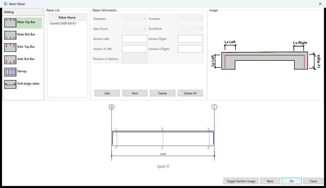
- Select Count:2-D20-S:0-E:1 in Rebar List; no row is selected in this capture, so fields have not loaded its values. 2. Diameter/Number and end fields belong to the selected definition. 3. Lx/Ly identify four anchorage legs. 4. These actions manage Main Top Bar only.
Main Bot Bar
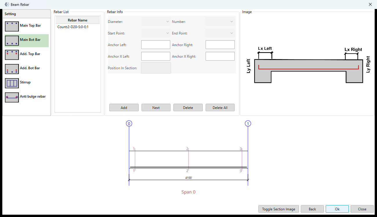
- Bottom main bars have a separate list. 2. Select a row to load type, count and Start/End. 3. The lower anchorage illustration differs from the top illustration. 4. These actions belong to Main Bot Bar.
Add. Top Bar
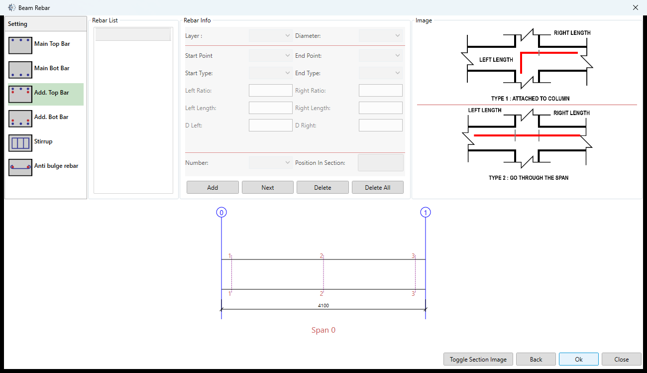
- The additional-top list is empty: use Add first. 2. Layer, Diameter and end types define the bar. 3. Ratio, Length, D Left/D Right and Number depend on the selected type. 4. The illustrations distinguish column attachment and crossing a span.
Add. Bot Bar
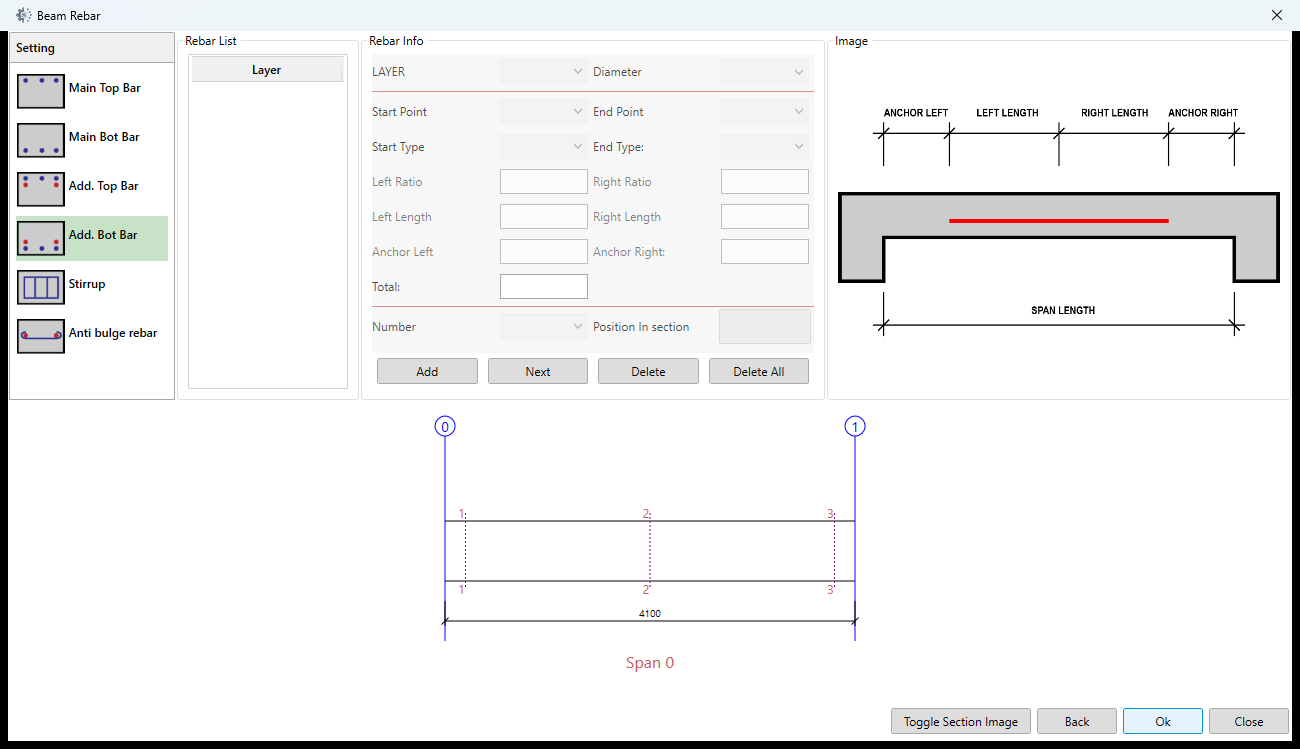
- Add/select an additional-bottom definition. 2. Its layer and ends are independent of top bars. 3. Read Ratio, Length, Anchor and Total together. 4. The diagram separates anchorage and left/right portions.
Stirrup Distribution
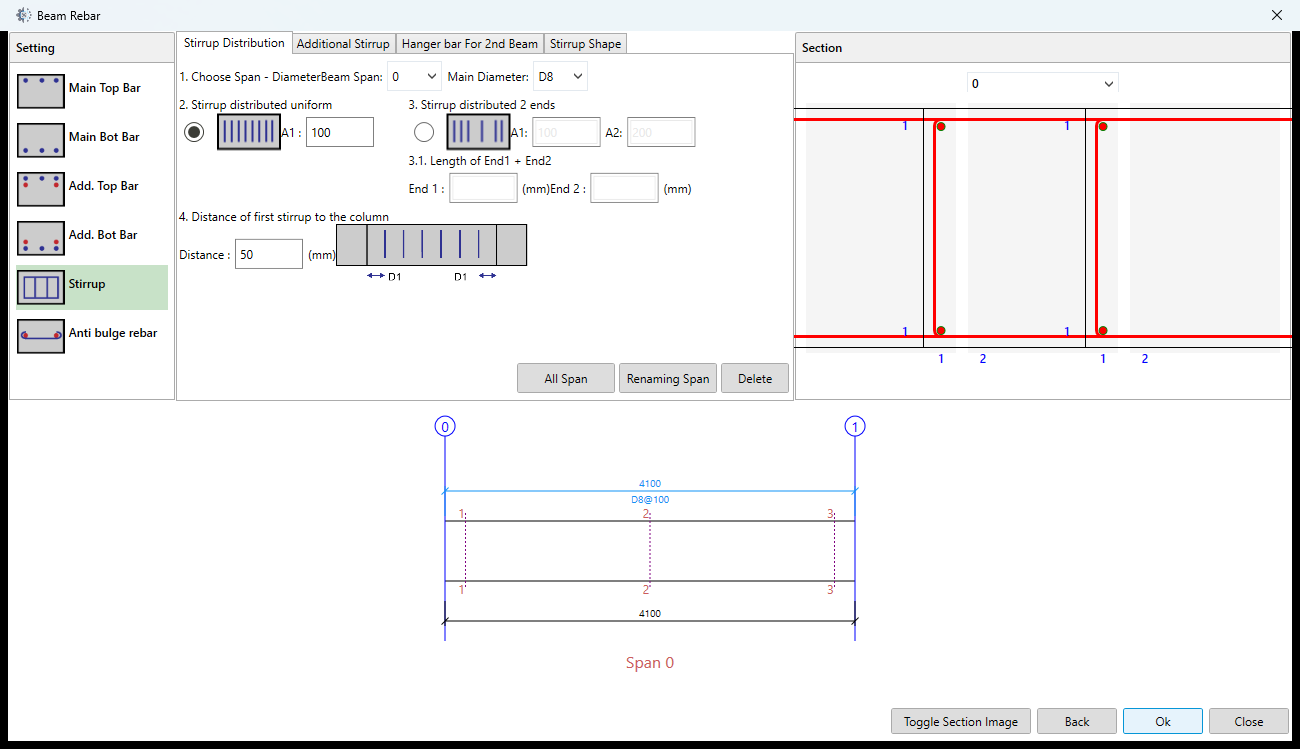
- Span 0, stirrup D8. 2. This editor uses uniform A1=100 mm; two-end mode and zone-length inputs are not enabled. 3. First-stirrup offset is 50 mm. 4. All Span/Renaming Span and Delete have different scopes; see the reference below.
Additional Stirrup
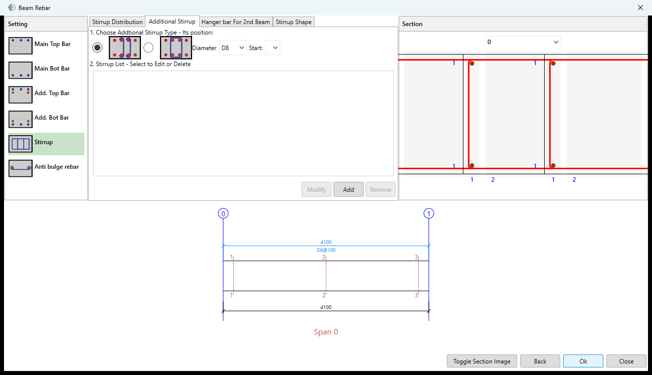
- Choose the illustrated additional type, diameter and permitted Start/End indices. 2. The list is empty. 3. Add is available; Modify/Remove require an existing selected definition.
Hanger bar For 2nd Beam
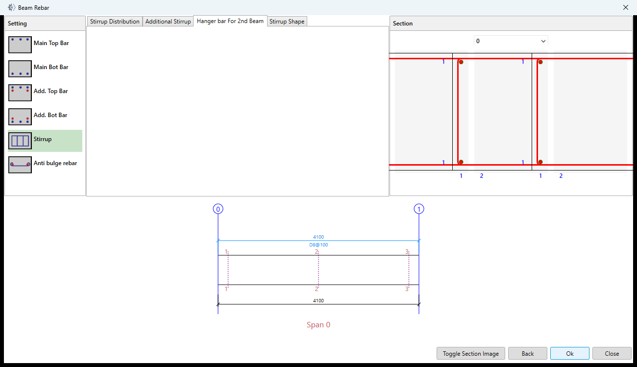
- Hanger bar For 2nd Beam was actually opened. 2. Its settings area is empty; it provides no hanger inputs or creation action here.
Stirrup Shape
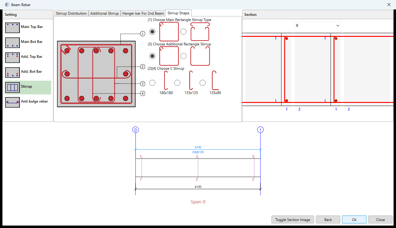
- Two main rectangular choices. 2. Two additional rectangular choices. 3. Three C-shaped illustrations labeled 180x180, 135x135, 135x90; each shape was not separately generated.
Anti bulge rebar
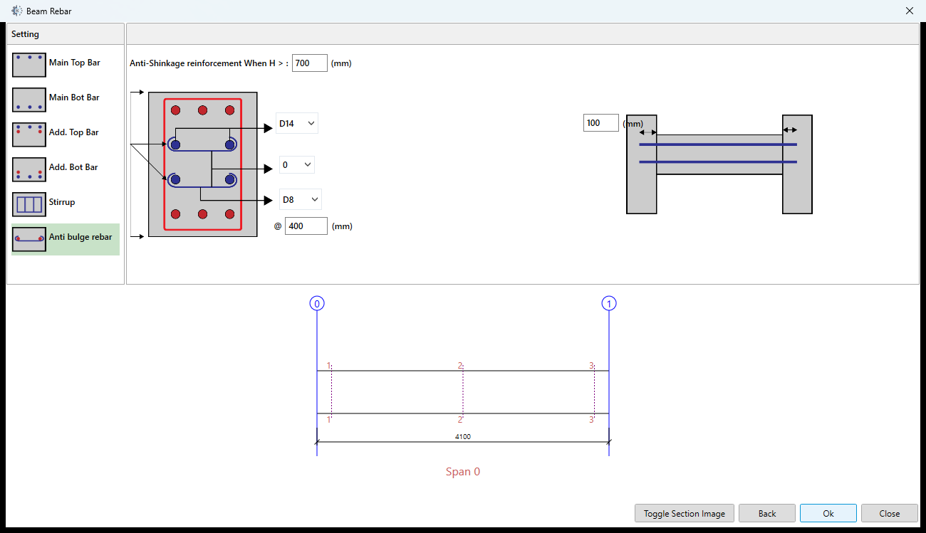
- Loaded height threshold 700 mm. 2. D14, 0 layers, D8 and @400 mm are separate inputs. 3. Column embed is 100 mm. This settings view does not establish that all side-bar configurations were generated.
Full-size R24 Quick Setting · Full Revit window.
From Quick Setting choose Go to Detail Rebar Forms. Select a reinforcement group on the left, then a row in Rebar List before editing. Use Add first when a group is empty; blank fields do not establish an applied configuration. The longitudinal diagram and sections are previews, not saved Rebar elements.
Main top and bottom bars
The two groups have the same controls but edit separate bar lists.
| Control | Use and inspection |
|---|---|
| Rebar List | Select the intended definition and match its highlighted path; it is not every bar in the layer. |
| Diameter | Rebar Bar Type of the selected definition. Check the created element's type in Properties. |
| Start Point / End Point | Editor run indices, not Revit Element IDs. Inspect which spans the bar crosses. |
| Number | Bars in this definition, not the number of rows in Rebar List. |
| Anchor Left / Anchor Right | Left/right anchorage legs shown in the diagram, mm. Change one end and check that end's shape. |
| Anchor X Left / Anchor X Right | X-direction anchorage legs at the two ends, mm; separate from the preceding pair. |
| Position In Section | Displays section positions; this button is disabled for both main-bar groups in the reviewed interface. |
| Add / Next | Add a definition or change the selected definition in this group. Check the selected row afterward. |
| Delete / Delete All | Remove the selected definition or this group's list in the editor. This is not a project-wide Revit Delete command. |
Additional top bars
| Control | Use and inspection |
|---|---|
| Rebar List; Add / Next / Delete / Delete All | Manage additional top bars independently of main and additional bottom bars. Select/add a definition before editing. |
| Layer | Layer and side among the currently available choices. Inspect section-dot positions. |
| Diameter; Number | Type and count of this definition, not all upper reinforcement in the beam. |
| Start Point / End Point | Select start/end run indices; available end shapes depend on these positions. |
| Start Type / End Type | Select each end's illustrated shape. Changing type can change which ratio or diameter-factor fields appear. |
| Left Ratio / Right Ratio | Dimensionless fractions of the corresponding span; 0.25 is one quarter, not 25 mm. Rounding and diameter-based additions also affect length. |
| Left Length / Right Length | Left/right lengths, mm. They interact with ratios; read the related field and diagram after editing either. |
| D Left / D Right | Diameter multipliers for the corresponding end type. For example, 30D of D20 is 600 mm, not a direct 30 mm input. |
| Position In Section | Select section positions for additional top bars, then check layer, dots and count. |
Additional bottom bars
| Control | Use and inspection |
|---|---|
| Rebar List; Add / Next / Delete / Delete All | Manage the independent additional-bottom list. |
| Layer; Diameter; Number | Layer, type and count of the selected definition. |
| Start Point / End Point; Start Type / End Type | Select the extent and both end shapes; do not apply one top-bar rule to every bottom-bar type. |
| Left Ratio / Right Ratio | Span-based cutoff ratios. Increasing a ratio can shorten the portion from midspan; a larger ratio does not always mean a longer bar. |
| Left Length / Right Length | Lengths on each side, mm, linked to ratio/anchorage values. |
| Anchor Left / Anchor Right | End anchorage lengths, mm. Inspect lengths and end indices together. |
| Total | Total linked to the left/right portions. Recheck all three values and the diagram after editing. |
| Position In Section | This button is disabled for additional bottom bars in the reviewed interface. |
Stirrups — four subtabs
| Tab / control | Use and inspection |
|---|---|
| Stirrup Distribution → Beam Span | Select the span first; displayed settings belong to that span. |
| Main Diameter | Main-stirrup type for the selected span. |
| Uniform distribution; A1 | One spacing, mm, in uniform mode. Two-end mode fields do not replace A1 in this mode. |
| Stirrup distributed 2 ends | Enable end zones; set end spacing, middle spacing and separate End1/End2 lengths, mm. Inspect both zone boundaries. |
| First-stirrup offset | Offset to the first stirrup, mm, distinct from spacing between stirrups. |
| All Span | Copies main diameter and end/middle spacing to other spans; additional arrangements copy only where section positions are compatible. It does not copy every zone length. |
| Renaming Span | This is the current English label, but the action copies configuration to higher-index spans while retaining each receiving span's End1/End2 lengths. It does not rename spans. |
| Main-stirrup Delete | Toggles main stirrups in the section diagram. Check the state before accepting; it is separate from Revit Delete. |
| Additional Stirrup → two type choices | Choose the illustrated type, Diameter and section-position Start/End indices. |
| Additional Stirrup → list; Modify / Add / Remove | Select a definition. Modify edits it, Add appends one, Remove removes that definition in the editor. |
| Hanger bar For 2nd Beam | Empty in the reviewed version; it is not an available, verified hanger-configuration form. |
| Stirrup Shape → Main Rectangle | Two illustrated main rectangular-stirrup choices. Inspect hook shape and created output. |
| Stirrup Shape → Additional Rectangle | Two additional rectangular-stirrup choices, separate from main stirrups. |
| Stirrup Shape → C-shaped group | Select the illustrated C-shaped option and inspect sections. The reviewed source assigns the same value to the last two options; distinct generated shapes have not been verified. |
Side-face reinforcement
Six inputs cover the beam-height H threshold, side-bar diameter, diameter of bars entering columns, column embed length, the @ spacing (lengths in mm), and 0–10 layers. Use the illustration and inspect sections. Zero layers requests no side-bar layer; this count is separate from top/bottom main-bar quantities.
Editor footer
Toggle Section Image shows/hides sections; it does not delete Rebar. Back returns to Quick Setting. OK accepts data for creation; Close/Esc closes without accepting that creation. After OK, inspect real Revit elements; an editor image does not prove the RVT was saved.
Inspect, edit and save
After successful generation in your version, select a top bar and a stirrup set in Revit. Check Host, Bar Type, Quantity, Spacing and the span/support role. Use Selection Box around the run, set Detail Level to Fine, and inspect upper/lower layers, cover, hooks and junctions. Dots in Quick Setting are schematic, not generated-bar counts.
For later edits, first identify that the bars belong to Classic and use the same variant on a copy. Initial creation and saved-result readback were verified; updating an existing cage and preserving manual edits were not. Use Undo to return from an unsuitable generation before testing another configuration; inspect model elements rather than assuming a closed dialog means success.
Revit Save / Save As retains model elements. The More settings gear manages Classic configuration; saving settings does not create a result RVT. No verified Classic result model is offered here. Practise on a project copy whose beams do not already carry new-tool reinforcement. The Beam Rebar guide explains Properties inspection, but its model is not Classic output.
Download the Revit 2027 input for practice on a copy: open input-school.rvt, use Manage → Select by ID for beam 427351, open a 3D view and verify the host does not carry new-tool reinforcement before choosing Classic. The package's alignment-result.rvt is beam-elevation output, not Classic reinforcement.