Beam Rebar Setting — field reference
This shared window stores current Beam Rebar rules for anchorage, cover, additional steel, section positions and shop splitting. It is separate from the span editor and Classic settings. Open BimSpeed.STR → Beam → Beam Rebar Setting, choose one of the four visible groups on the left and scroll inside that group.
The field-reference screenshots were captured in Revit 2027.3; the Save → reopen example below was checked separately in Revit 2024.3. The tables cover 50 editable/selectable controls in the four visible groups, not 50 generation tests. Save → reopen → regenerate has not been verified for every field. Captured values are loaded configuration, not design recommendations.
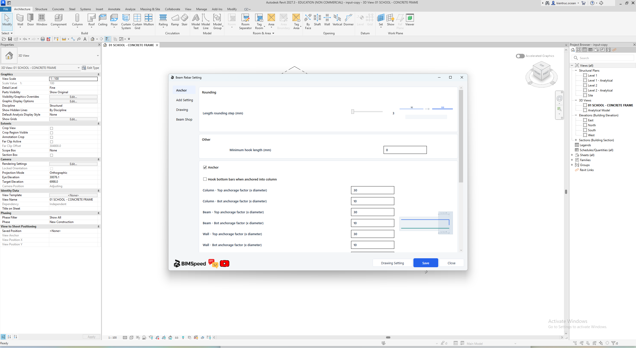
Anchor

- Choose a group on the left; the right-hand scrollbar belongs to the current group.
- Rounding and Minimum hook length are lengths inmm.
- Enable Anchor, choose bottom-bar hooking at columns and enter the factors for the actual support type. Factors multiply diameter; they are not lengths inmm.
- Drawing settings opens a separate window. Save stores configuration and closes; Close leaves this window.
| Field / option | Unit / condition | Effect and inspection |
|---|---|---|
| Length rounding step | mm; slider 0–500 | Step used when rounding calculated lengths. Compare the detailed editor before/after; the 92→100 sketch is illustrative, not a model measurement. |
| Minimum hook length | mm | Minimum hook for applicable groups. Zero can select a diameter-based rule; it does not remove all hooks. |
| Anchor | on/off | Enable support-type anchorage rules below. Inspect upper/lower anchorage separately; enabling it does not verify anchorage adequacy. |
| Hook bottom bars when anchored into column | on/off | Apply the configured bottom-bar hook at columns. Inspect the column junction; this is separate from other bar-group hook options. |
| Column — Top anchorage factor | × bar diameter | Factor for top bars anchoring into columns. For example 30×D20 gives 600 mm for the factor-based part before other geometric adjustments. |
| Column — Bot anchorage factor | × bar diameter | Independent bottom-bar factor at columns. It does not change the top-bar factor; inspect a bottom-bar end. |
| Beam — Top anchorage factor | × bar diameter | Used for top bars supported by another beam; verify the recognized support type. |
| Beam — Bot anchorage factor | × bar diameter | Bottom anchorage at beam supports, independent of top bars and column supports. |
| Wall — Top anchorage factor | × bar diameter | Factor-based top anchorage into wall supports; inspect the portion inside that support. |
| Wall — Bot anchorage factor | × bar diameter | Bottom anchorage at walls; equal displayed values do not make this the column setting. |
| Foundation — Top anchorage factor | × bar diameter | Top-bar factor at foundation supports. Scroll down within Anchor to reach it. |
| Foundation — Bot anchorage factor | × bar diameter | Bottom-bar factor at foundation supports; inspect support geometry and the bar end together. |
| Maximum beam step for bent bars | mm | Threshold for treating a small step as a bent-bar continuation; it is not slope or anchorage length. Inspect both sides of the step. |
| Concrete cover c | mm | Cover used with stirrup/main diameters to place bars. Check the section and host. |
| Clear distance between layers a | mm | Clear layer gap, not centre spacing. Increasing it moves the inner layer farther inward; check available section depth. |

- Scroll to foundation factors. 2. Step threshold. 3. Cover and clear layer gap; do not substitute centre spacing for the clear gap.
Add Setting

- Choose Bar Spacer or C Stirrup, then use its enabled type/spacing pair. 2. Side bars/cross ties: minimumH, the two bar types, tie spacing and support extension. Scroll further for length rules and hangers.
| Field / option | Unit / condition | Effect and inspection |
|---|---|---|
| Spacers | on/off | Enable spacer generation, then choose one form below. Disabling the group omits the spacer request, not the beam. |
| Bar Spacer | single-choice mode | Choose bar spacers; use the bar-spacer diameter/spacing fields for this mode. |
| C Stirrup | single-choice mode | Choose C-tie spacers; use C-tie diameter/spacing rather than the bar-spacer pair. |
| Spacer bar diameter | Rebar Bar Type | Bar type for bar spacers, populated from the model. Type and spacing are separate. |
| Spacer bar spacing | mm | Along-beam spacing for bar spacers; reducing2000→1000 requests denser placement. Recount generated elements. |
| C-tie diameter | Rebar Bar Type | Type for C-tie spacers, applicable to the C Stirrup mode. |
| C-tie spacing | mm | Independent C-tie spacing; greyed fields of the other mode are not its applied spacing. |
| Minimum beam depth H | mm | Depth threshold for the side-bar/cross-tie group. Beams below it do not have the same request; inspect the editor state. |
| Side bar diameter | Rebar Bar Type | Type of longitudinal side bars, separate from main top/bottom bars. Inspect both side faces. |
| Cross-tie diameter | Rebar Bar Type | Type of transverse cross ties, distinct from the side longitudinal bars. |
| Cross-tie spacing | mm | Cross-tie spacing along the beam. Increasing400→500 requests a sparser layout; inspect actual sets and spacing. |
| Anchorage into support | mm | Direct support extension for this group, separate from ×D anchorage factors. |
| Span bars: divisor N in L/N + k*d | divisor; N > 0 | The span-related length contribution is L/N. Larger N shortens that part for the same L; N is not a bar count. |
| Span bars: coefficient k | factor ×D | Additional k×diameter contribution. Zero omits that addition, not the entire span bar. |
| Support layer 1: divisor N | divisor; N > 0 | L/N for first-layer support additions. Changing3→4 shortens the span-based portion; layers 2/3 have separate fields. |
| Support layer 1: coefficient k | factor ×D | Diameter-based addition for support layer 1, combined with L/N and endpoint treatment. |
| Support layer 2: divisor N | divisor; N > 0 | Independent L/N for second-layer support additions; the corresponding layer must exist in the layout. |
| Support layer 2: coefficient k | factor ×D | Diameter addition for layer 2; it does not change its quantity. |
| Support layer 3: divisor N | divisor; N > 0 | Independent L/N for a third support layer when present. Entering a factor does not itself enable that layer. |
| Support layer 3: coefficient k | factor ×D | Diameter addition for layer 3; inspect the matching bar row in the editor. |
| Additional stirrup count | count | Tie count in the additional region. It is separate from spacing; inspect each side when the editor splits a junction into sides. |
| Additional stirrup spacing | mm | Spacing within the additional region. With the same count, smaller spacing makes that region shorter/denser; inspect its actual extent. |
| Hanger Bar | on/off | Enable hanger bars at recognized/selected secondary-beam junctions; this is separate from additional ties. |
| Hanger extension each side | mm | Extension on each side of a hanger.300 is not the combined extension of both sides. |
| Hanger bar count | count | Hanger quantity at the junction, separate from the secondary beam longitudinal bars. |
| Hanger bar diameter | Rebar Bar Type | Choose the hanger type; inspect bend geometry and the created element type. |
| Place stirrups on the beam segment inside the foundation | on/off | Request stirrups on the beam portion inside the foundation/pile cap. Inspect that overlap, not just the free span. |
| Foundation stirrup spacing | mm | Spacing for the embedded portion when enabled above, separate from end/middle spacing outside it. |
For the length-rule group, L/N + k×D contributes to bar length; it is not a quantity. With L=6000 mm and k=0, changing N=3→4 reduces the L/N part from 2000 to1500 mm; hooks, anchorage, diameter and support treatment can still change total length. Change one group at a time and compare its bar row in the editor.

- Layer 2/3 rules and additional ties. 2. Hangers: enable, extension each side, quantity and type. 3. Stirrups inside foundations and their own spacing.
Drawing
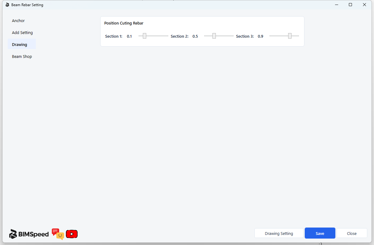
| Field / option | Unit / condition | Effect and inspection |
|---|---|---|
| Section 1 | ratio0.05–0.30 | Section position as a fraction along the beam;0.1 means10%, not100 mm. |
| Section 2 | ratio0.35–0.80 | Middle section position;0.5 is halfway along the beam curve. Inspect its marker in the longitudinal view. |
| Section 3 | ratio0.70–0.99 | End section position along the location-curve direction. Reversing the host can reverse the left/right interpretation. |
These are positions along the beam, not print scales such as1:25 or1:75. Use Drawing settings at the bottom for dim/tag/template and sheet options in the Drawing/Detail/Section reference. Opening it does not create a sheet.
Beam Shop
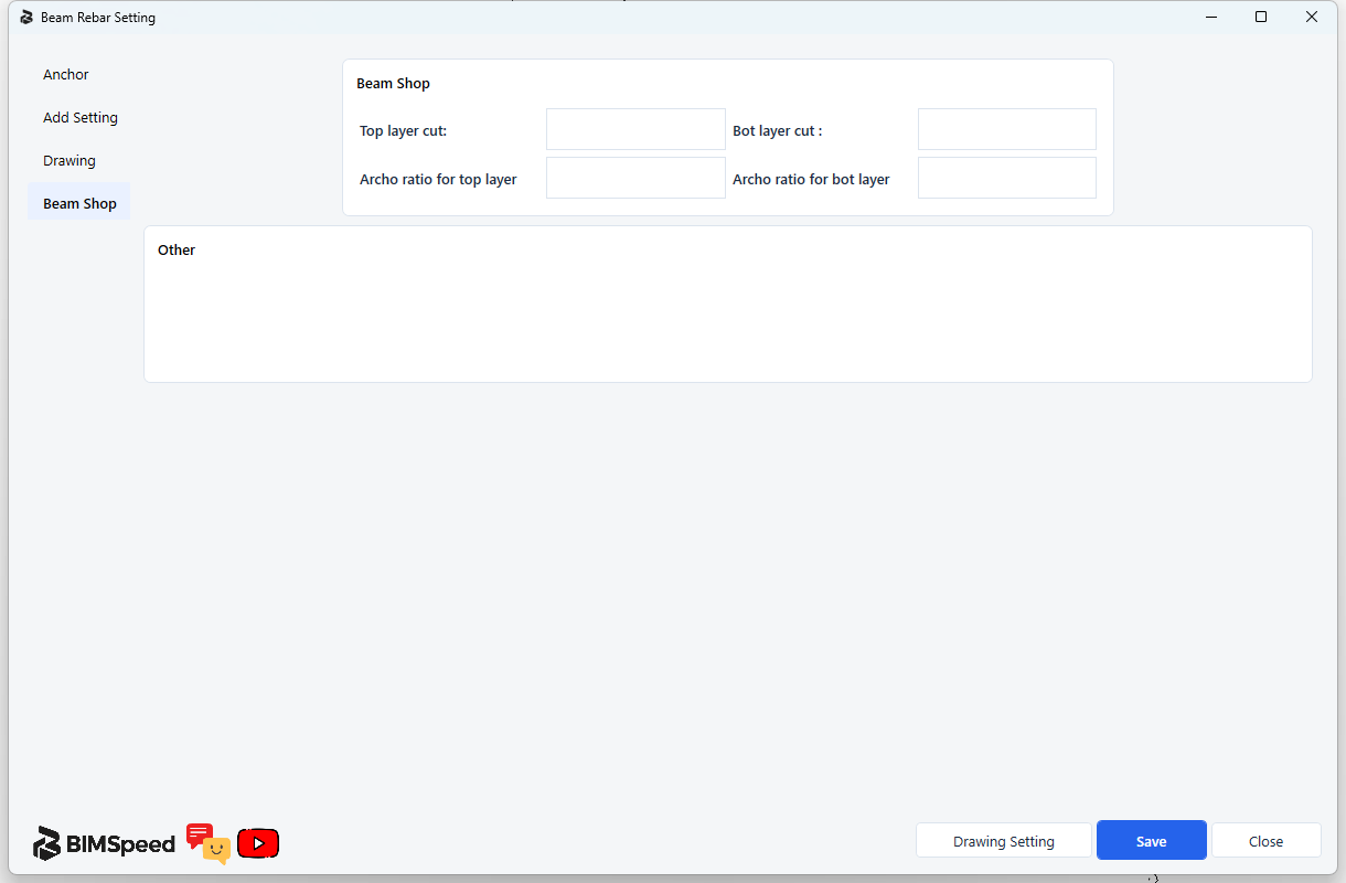
| Field / option | Unit / condition | Effect and inspection |
|---|---|---|
| Top layer cut | span ratio | Span-based split position for top reinforcement, not a BeamCut stock-bar length. |
| Bot layer cut | span ratio | Independent bottom-layer split position; inspect proposed shop segments before applying. |
| Archo ratio for top layer | factor ×D | Top shop lap/anchorage factor. The English UI spells the label “Archo”; use the correct row and do not enter mm as a factor. |
| Archo ratio for bot layer | factor ×D | Independent bottom shop lap/anchorage factor; inspect the lower-bar overlap after splitting. |
The Shop fields are empty in the capture; emptiness is not a verified valid configuration or proof of successful splitting. The Other group currently has no inputs. Optimization, stock reservation and actual-cut confirmation belong to BeamCut, separately from these factors.
Verified Save → reopen example
In Revit 2024.3, installed release 2026.10.23.2046, Length rounding step (mm) was changed from 3 to 50, saved with Save, and checked in a newly opened settings window. The retained value was 50 mm, as shown below. This verifies settings persistence; it does not verify reinforcement generated with a 50 mm rounding step. The original configuration was restored after the check.

- Choose Anchor on the left.
- Read the value beside Length rounding step (mm). The tested value 50 mm remained after reopening.
- Save stores configuration and closes the window. Open Beam Rebar Setting again to verify it; a closed window alone is insufficient.
Prepare beam parameters
Earlier menus called this Create beam rebar parameters V2. In the current menu use BimSpeed.GEN → Link → Create Shared Parameters, or the same command in BimSpeed.STR → Utilities. It prepares project data; it is separate from this window's Save button and from generating Rebar. The shared-parameter guide is the canonical command reference.
- Make an RVT copy and record beams currently marked BS Secondary Beam = Yes. This setup does not ask for a beam-run selection to limit its effects.
- Inspect Manage → Project Parameters and the Properties of a representative beam before running. Do not create another parameter with the same name and a different GUID to conceal a missing binding.
- Run Create Shared Parameters. The supplied beam definitions require
BS_Data_Beam.txt; the BeamStructural and BeamRebar groups are bound to Structural Framing as Instance parameters displayed under Text. Other generic parameters created by this command can use different types/bindings; this beam-specific description does not apply to all of them. - After completion, recheck Project Parameters and actual beam Properties. Examples:
BS Secondary Beamis Yes/No;@BS_Beam Group,@BS_RB_Top.L1,@BS_RB_Bot.L1and@BS_RB_Stirrup.Middleare text fields. An empty new field does not mean reinforcement has been created or quantities updated.
Secondary-beam effect: besides adding missing bindings, the reviewed version sets BS Secondary Beam to No on every Structural Framing instance whose field is writable, including existing Yes values. This is not an add-only operation that preserves all values. Recheck and restore the intended secondary-beam flags before using secondary-beam/hanger workflows. “Create Shared Parameter completed” alone does not prove all bindings succeeded; verify category, GUID, data type and the actual beam values.
After checking the data, reopen Beam Rebar for run selection and reinforcement creation/editing, then Save As a separate RVT. The binding behavior above was reviewed, but this documentation set has no separate before/after execution capture for the setup command; it is not a newly verified runtime case.
Save, apply and inspect changes
- Record the current configuration before broad changes. Compare one small edit, such as the top-column factor 30→35 or spacer spacing 2000→1000 mm, while keeping other fields fixed. These examples describe software effects only.
- Press Save. The window closes and configuration is stored. Reopen it to check the retained value; the rounding example above exercised this save round trip.
- Reopen Beam Rebar or Axis, choose the intended run/span and check whether the editor/preview received the change. Bar/span overrides can differ from shared defaults; inspect scope before regeneration.
- After updating with the correct tool, select a bar in the affected group and inspect its quantity, length, layer, hook or spacing in Revit. Saving settings alone does not update existing bars. Save As a separate result RVT and reopen it.
- If unsuitable, Undo the model transaction and restore/save the recorded configuration. Revit Undo is not a substitute for restoring settings stored outside the model.
Use copies of the models in the Beam Rebar and Axis guides for practice. This settings-only capture adds no verified result RVT and does not establish that every generation branch was exercised.