Spread Footings — Reinforcement Settings
English Revit 2027.3 demonstration. Verification: Actual footing and command run captured; generated bar count still needs independent Revit confirmation.
Video
Narration: Google Gemini Charon, professional English. The video retains the full Revit screen, briefly zooms on named controls, and includes timed English subtitles. Transcript · SRT.
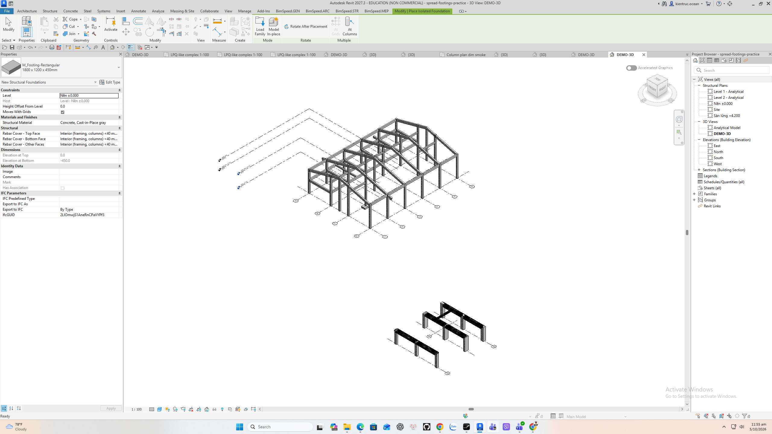
1. Place and select a real footing
Place a native rectangular isolated footing at a structural column. This example uses the one thousand eight hundred by one thousand two hundred by four hundred fifty millimeter type at level Nền zero. Select the footing edge, then choose BimSpeed dot S T R, Isolated Footing, and the classic Isolated Footing command.
2. Set cover and enable layers
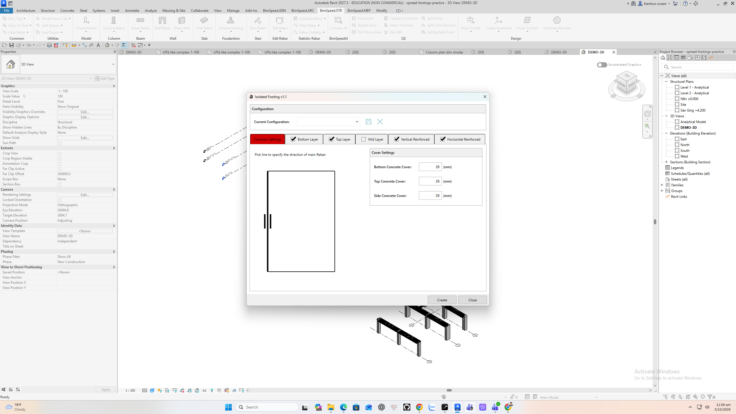
Common Settings sets bottom, top and side concrete cover, here thirty five millimeters. Each reinforcement tab has an enable checkbox. Start with only the bottom layer enabled for a simple run. Store a named configuration only after checking the footing dimensions and available bar types.
3. Bottom and top meshes
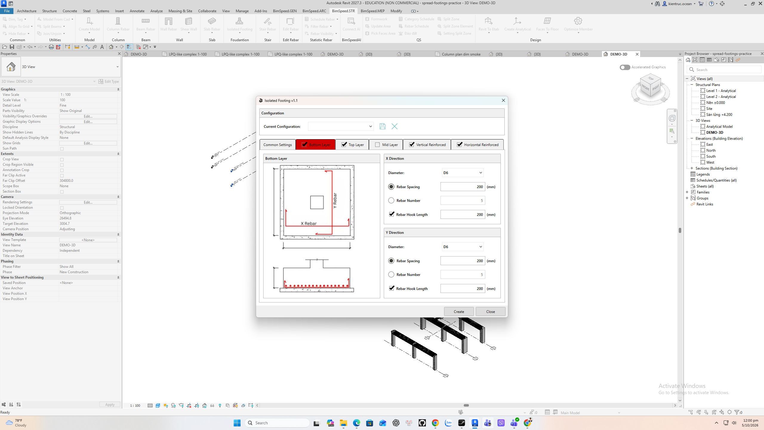
Bottom Layer has independent X and Y diameter, spacing or bar number, and optional hook length. The displayed example is D six at two hundred millimeters in each direction with two hundred millimeter hooks. Top Layer repeats these controls for the upper mesh. Switch off Top Layer when it is not required by the design.
4. Mid and vertical bars
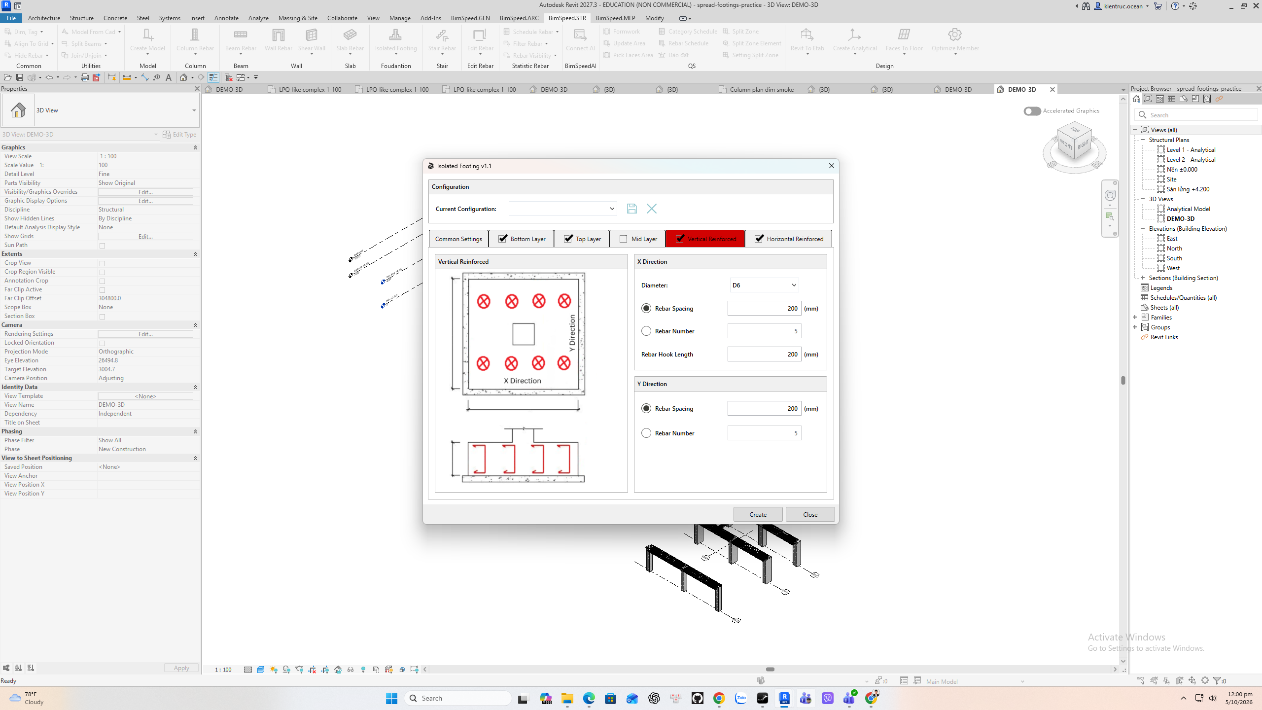
Mid Layer is disabled in this example. Enable it only when an intermediate mesh is intended. Vertical Reinforced controls X and Y starter or vertical bars with diameter and spacing or number. Review the preview, anchorage and the host column before creating bars.
5. Horizontal perimeter bars and run
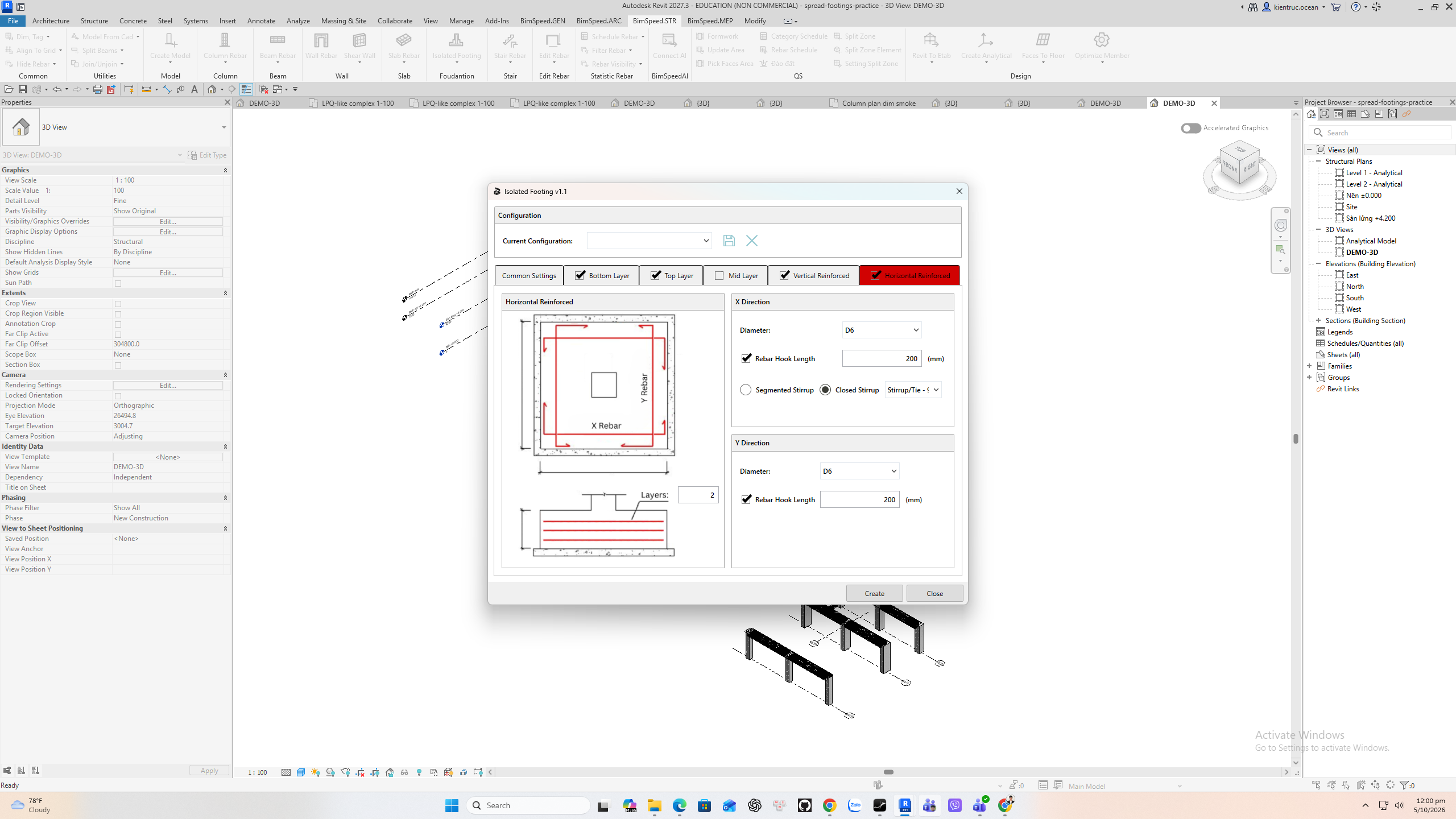
Horizontal Reinforced can create segmented or closed stirrups around the footing, with diameter, hook length and layer count. In the captured run, Top, Vertical and Horizontal were disabled so Create requested the bottom mesh only. The dialog closed after Create, but this footage alone does not prove the resulting bar count. Confirm Rebar elements in the saved model before treating the result as a verified detail.
Independent count in Revit 2024.3
The educational footing case enabled Bottom Layer only, selected D12 in both directions, used 200 mm spacing and 35 mm covers, and disabled bends. The reinforcement processor committed 2 sets with Quantities 10 and 12, totalling 22 bars, hosted by the footing family. These are actual Rebar element quantities rather than preview counts.
Geometry did not pass: both sets have the warning “Rebar is placed completely outside of its host”. A duplicate Mark warning also involves the footing family and an auxiliary element created by the processor. Check the bottom face, distribution direction and actual host before using the result. The cause has not been established as a product or geometry-adapter issue. This run called RebarFactory and did not execute the ribbon entry.
English UI: 1 enable required layers using the tab checkboxes; 2 bottom/top/side covers in mm; 3 pick a diagram edge to set the main-bar direction. The 35 mm values are illustrative and must be checked against the host requirements.