U-Boot Slab Review — geometry and scope
Select one existing Floor, then open U-Boot Slab Review in the BimSpeed.STR slab group or the standalone module Review button. Ribbon visibility depends on edition/module; package registration does not prove every edition shows the button. Review and Rebar share a shell with different starting tabs.
Shared window, every action and steel setting · U-Boot reinforcement
Walkthrough
- Read Floor boundary/holes, thickness, elevation and supports. The support reader accepts eligible vertical prismatic structural columns; curved/slanted supports, walls, beams and links require separate review.
- Adjust Inputs or Catalog when available. Review diagnostics and local U/V preview; apply edited Advanced JSON.
- Create/update geometry, close the window and inspect actual elements in a Revit 3D view. Preview/review export is not model output.
- Open Rebar after geometry is correct, resolve types, check readiness and create steel. Remove owned steel before updating unit geometry.
Choose a catalog item and inspect a concrete example
- Select one Floor and open U-Boot Slab Review. Read its boundary/openings and thickness. Model accepts external family/catalog locations; Browse alone does not apply an item. After a path change, use Catalog → Reload catalog from Model path.
- Choose series/assembly/body height, UP/DOWN and feet, then Use catalog selection. Single has one unit per assembly; Double has upper/lower units. Inspect Inputs after Use: selection changes dimensions/layout, not Floor thickness. Renaming catalog provenance cannot make an unrelated family valid.
- Verified example: Double H230,520×520 mm outer footprint,130/100 mm upper/lower bodies, zero feet,50/120 mm bottom/top skins,300 mm ribs and 820 mm pitch in a 400 mm Floor. Rotation 17°, edge clearance 150 mm. Zero feet do not remove the bottom skin: the body remains elevated from the soffit. The family includes a 10 mm top spacer; inspect its actual full bounding box rather than body height alone.
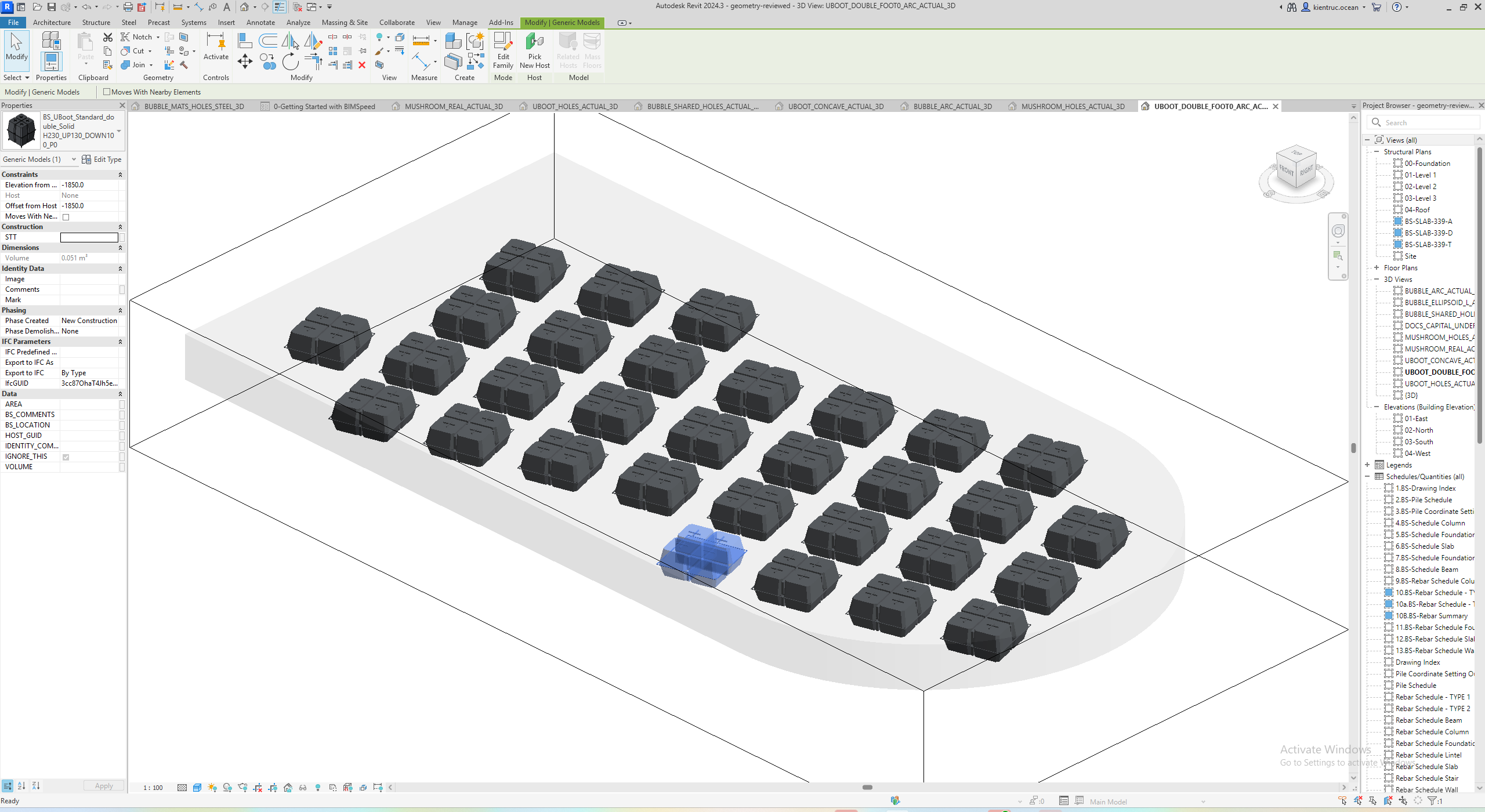
- The final preview has 31 assemblies /62 units. The writer creates 31 FamilyInstances; each double assembly contains both halves.31 is not the unit count. Inspect curved edges/openings as well as the total. Solid-family volume differs from the rectangular envelope and is not plastic volume.
- Create / Update writes positive family instances without cutting the Floor. Close the tool and open the host's 3D/plan; select an instance and inspect Family/Type, dimensions and elevations, including body/feet/spacer. Ctrl+S and reopen. This scoped geometry update is separate from editing a shared family type throughout the project.
To reduce count, increase pitch together with rib clearance; changing only one leaves an invalid mismatch. Increasing Edge clearance can remove rows/candidates: review openings/supports afterward. For a denser-layout exercise, reduce pitch/ribs within valid input relationships and inspect counts and real ribs; this does not approve structural dimensions. Follow the shared workflow to remove/regenerate owned steel after product-geometry changes.
Geometry settings
| Control / setting | Unit, condition, effect and verification |
|---|---|
Catalog / Series-assembly-body height / UP-DOWN / Foot height | Select the catalog row, upper/lower pair and foot height, then Use catalog selection. Single has one body; double has two. Selection alone does not apply the row. |
Use catalog selection / Reload catalog from Model path | Use copies dimensions and recalculates top skin/pitch without resizing the Floor. Reload reads the Model path or embedded catalog. |
CatalogProvenance / CatalogVersion / CatalogItem | Source, version and row Id must match the family. These provide traceability, not supplier approval. |
Assembly | Single/Double; distinguish assembly count from unit count in a double layout. |
OuterLengthMm / OuterWidthMm | Outside X/Y envelope shared by both halves; affects footprint, pitch and ribs. |
UnitBodyHeightMm / LowerUnitBodyHeightMm / TotalVoidHeightMm | Upper/lower body heights exclude feet. Total void height must match the assembly; lower=0 retains legacy equal-half semantics, so prefer an explicit catalog selection. |
LegHeightMm / BottomSkinMm / TopSkinMm | Foot and concrete skins in mm. Nonzero feet match the bottom skin; zero feet still need positive skin and independent support design. Check total depth and top-spacer clearance. |
RibClearXmm / RibClearYmm / PitchXmm / PitchYmm | Clear ribs and center pitch in mm: pitch equals outer size plus corresponding clear rib. Keep both inputs consistent. |
RotationDegrees / GridOriginMm.X,Y / OffsetXmm / OffsetYmm | Angle and local coordinates; offsets follow rotated grid axes. Check edge/opening rows. |
EdgeClearanceMm | Unit setback from boundary/holes in mm. Increasing it shrinks the allowed area; inspect rejected candidates. |
SolidExclusions[].Support / ClearanceMm | Advanced: actual support reference or explicit ManualSolid polygon, plus clearance. Every supplied footprint excludes units regardless of elevation. |
MaximumCandidates | Maximum candidates; an excessively dense grid must be diagnosed rather than presented as a complete partial layout. |
Verification, saving and limits
Positive geometry does not cut the Floor: envelope volume is neither plastic volume nor net concrete deduction. Save stores JSON; save the RVT separately. Reopen the command after host/support changes to refresh its snapshot. Cover changes cannot resolve stale-host errors.
Geometry evidence and download
Installed package 2026.10.23.2046, production service in Revit 2024. Geometry was created/updated, saved and reopened without void-cutting the original Floor. The ribbon entry was not invoked.
| Geometry case | Create | Same-input repeat | Update |
|---|---|---|---|
| Single — openings | 56 | 56 | 41 |
| Single — concave boundary | 26 | 26 | 21 |
| Double, zero feet — arc boundary | 38 | 38 | 31 |
U-Boot uses solid family instances; these counts are FamilyInstances per assembly, not the Double unit count, not plastic volume. The zero-foot double case checks geometry only and requires independently designed support.
Marker 1 identifies inputs, committed model geometry and selected-element Properties respectively. The input UI and geometry output are separate cases; Mushroom’s empty-support preview is not evidence of created drops.


Revit 2024 input/positive-geometry output package. Open the ACTUAL_3D/ACTUAL_PLAN views and read the per-host quantities/limits in README. Save/reopen completed before full-window capture was interrupted after five views; remaining angles/capital close-ups are not claimed.
Mark 1 identifies series/assembly/body, UP/DOWN and foot choices. Mark 2 separates Use catalog selection (apply choices to Inputs) from Reload catalog from Model path (reread the catalog). Changing a row alone does not establish that Inputs were applied.

After scrolling Inputs: 1 contains body/lower/void, foot and skins; 2 contains rib clear, pitch and rotation; 3 contains origin/offset, edge clearance and candidate limit. Check total height against thickness, including the separate 10 mm top spacer within the top skin.

Inspect a reopened Double element
1: Properties identifies one BS_UBoot_Standard_double_Solid Generic Model family instance, type H230_UP130_DOWN100_P0, and that instance volume. Host=None is expected for this independently placed family; the tool associates it with the selected Floor for Update. 2: the selected assembly contains two bodies. This case has 31 assemblies/62 units;62 is not the FamilyInstance count, and envelope is not plastic volume. This arc-edge, zero-foot example differs from the Single settings image.